|
| |
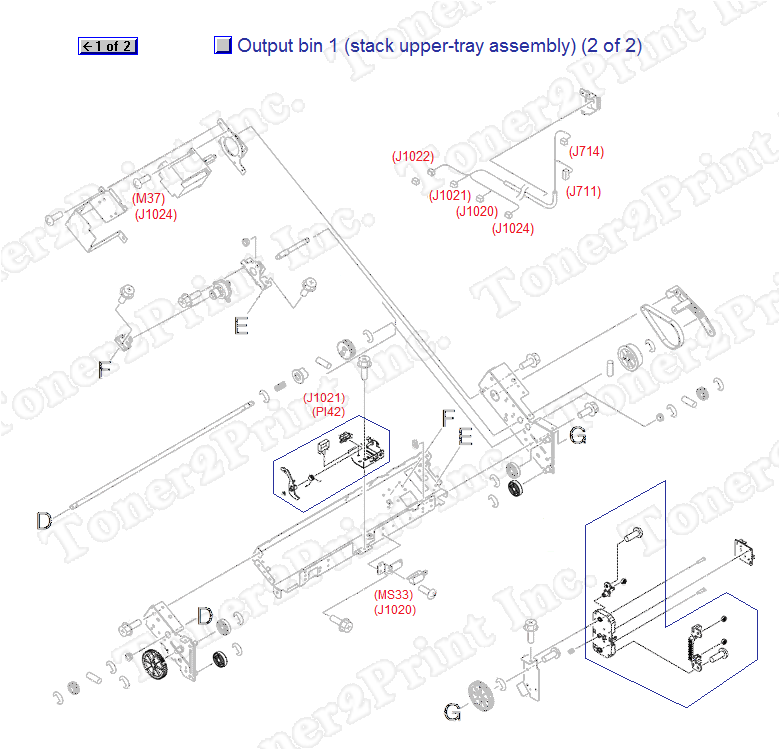
4G1-1498-000CN is represented by #5 in the diagram below.
Output bin 1
- 1
- 1 RM1-4101-000CN - Stapler/stacker tray - Upper tray assembly for the stapler/stacker (output bin 1)
- 1 RM1-4101-020CN - Stapler/stacker tray - Upper tray assembly for the stapler/stacker (output bin 1)
- 3
- 3 FU5-0435-000CN - 44-tooth gear - Mounts on the front tray side plate attached to the upper tray cross member
- 5
- 5 4G1-1498-000CN - Area sensor PCA assembly - Located on the area sensor holder assembly
- 6
- 6 FM2-0707-000CN - Paper sensor assembly - Includes the paper sensor arm, photo interrupter (PI42), and paper sensor plate
1
RM1-4101-000CN
Tray
Stapler/stacker tray - Upper tray assembly for the stapler/stacker (output bin 1)
1
RM1-4101-020CN
Tray Assembly
Stapler/stacker tray - Upper tray assembly for the stapler/stacker (output bin 1)
3
FU5-0435-000CN
Gear
44-tooth gear - Mounts on the front tray side plate attached to the upper tray cross member
5
4G1-1498-000CN
Sensor
Area sensor PCA assembly - Located on the area sensor holder assembly
6
FM2-0707-000CN
Sensor
Paper sensor assembly - Includes the paper sensor arm, photo interrupter (PI42), and paper sensor plate
|
|