| |
RM1-4113-000CN is represented by #1 in the diagram below.
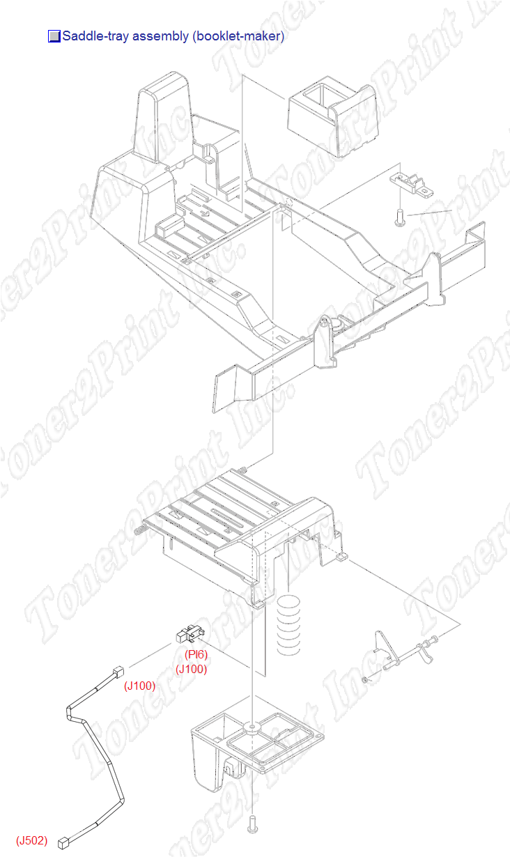
Saddle-tray assembly
- 1
- 1 RM1-4113-000CN - Booklet-output bin (saddle tray assembly) - Includes sensor cable and photo interrupter (TLP1242)
- 2
- 2 4G1-2285-000CN - Sensor cable - Located on the saddle tray assembly - Connects on the photo interrupter (TLP1242)
- 3
- 3 WG8-5593-000CN - Sensor PC board - Small board with flag activated photosensor
1
RM1-4113-000CN
Tray Assembly
Booklet-output bin (saddle tray assembly) - Includes sensor cable and photo interrupter (TLP1242)
2
4G1-2285-000CN
Cable
Sensor cable - Located on the saddle tray assembly - Connects on the photo interrupter (TLP1242)
3
WG8-5593-000CN
PC Board
Sensor PC board - Small board with flag activated photosensor
|