| |
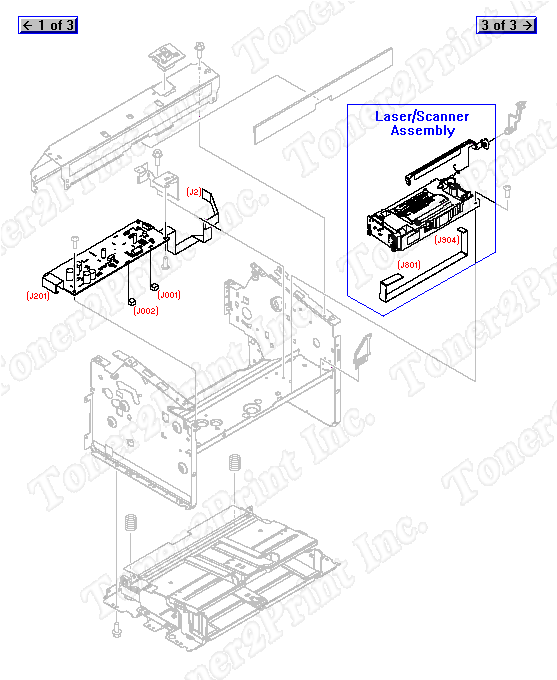
RM1-2309-000CN is represented by #4 in the diagram below.
Internal Components
- 3
- 3 RM1-2033-000CN - Laser/scanner assembly - Mounts on the front support shelf on the printer frame assembly - Mounts just below the engine control unit PC board
- 3 RM1-2033-030CN - Laser/scanner assembly - Mounts on the front support shelf on the printer frame assembly - Mounts just below the engine control unit PC board
- 4
- 4 RM1-2309-000CN - Engine Control Unit (ECU) PC board - Provides timing and control of the printer motor and functions - Mounts on the front support shelf of the printer frame assembly (just above the laser/scanner assembly)
3
RM1-2033-000CN
Laser Scanner
Laser/scanner assembly - Mounts on the front support shelf on the printer frame assembly - Mounts just below the engine control unit PC board
3
RM1-2033-030CN
Laser Scanner
Laser/scanner assembly - Mounts on the front support shelf on the printer frame assembly - Mounts just below the engine control unit PC board
4
RM1-2309-000CN
PC Board
Engine Control Unit (ECU) PC board - Provides timing and control of the printer motor and functions - Mounts on the front support shelf of the printer frame assembly (just above the laser/scanner assembly)
|