| |
RG5-5395-000CN is represented by #5 in the diagram below.
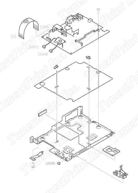
Electrical Components
- 5
- 5 RG5-5395-000CN - ECU board - Engine controller unit/power system controller board - Logic and power supply combined PCA - 110V
- 6
- 6 RH2-5381-000CN - Flex cable - Has two 20-pin (M) edge connectors - 8.2cm (3.2in) long
- 7
- 7 RB2-3985-000CN - Insulating sheet - Between ECU PC board and metal pan
- 8
- 8 RB2-3984-000CN - ECU plate (L-shaped) - Metal plate that supports engine controller PC board
- 9
- 9 RB1-7303-000CN - Stand-off spacer between ECU PC board and metal ECU pan
- 9 RB1-7303-000CN - Stand-off spacer between ECU PC board and metal ECU pan
5
RG5-5395-000CN
PC Board
ECU board - Engine controller unit/power system controller board - Logic and power supply combined PCA - 110V
6
RH2-5381-000CN
Cable
Flex cable - Has two 20-pin (M) edge connectors - 8.2cm (3.2in) long
7
RB2-3985-000CN
Insulator
Insulating sheet - Between ECU PC board and metal pan
8
RB2-3984-000CN
Plate
ECU plate (L-shaped) - Metal plate that supports engine controller PC board
9
RB1-7303-000CN
Spacer
Stand-off spacer between ECU PC board and metal ECU pan
9
RB1-7303-000CN
Spacer
Stand-off spacer between ECU PC board and metal ECU pan
|