|
| |
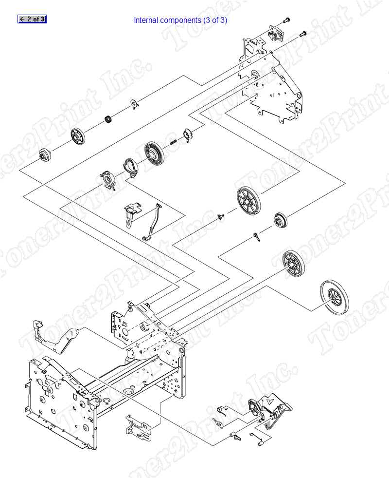
RC1-2494-000CN is represented by #5 in the diagram below.
Internal components
- 2
- 2 XA9-1495-000CN - 4 Wafer head machine screw included - M3, 6mm long, No. 2 Phillips recess - Secures metal to sheet metal
- 3
- 3 XA9-1420-000CN - M3 pan head phillips screw with captive flat and split-lock washers - 8mm long
- 4
- 4 RC1-2485-000CN - Lower coupler link - Connects between the toner cartridge drive gear disengaging cam and the top link coupler (bracket)
- 5
- 5 RC1-2494-000CN - Top coupler link - L-shaped plastic bracket - Pulls the the lower coupler link to disengage to toner cartridge drive gear
2
XA9-1495-000CN
Screw
4 Wafer head machine screw included - M3, 6mm long, No. 2 Phillips recess - Secures metal to sheet metal
3
XA9-1420-000CN
Screw
M3 pan head phillips screw with captive flat and split-lock washers - 8mm long
4
RC1-2485-000CN
Link
Lower coupler link - Connects between the toner cartridge drive gear disengaging cam and the top link coupler (bracket)
5
RC1-2494-000CN
Link
Top coupler link - L-shaped plastic bracket - Pulls the the lower coupler link to disengage to toner cartridge drive gear
|
|