|
| |
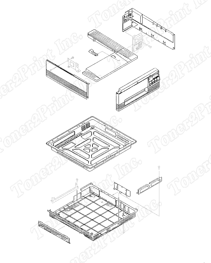
RA1-8290-000CN is represented by #4 in the diagram below.
- 1
- 1 RF1-2575-000CN - Right side panel - Also includes part of top and rear panels
- 5
- 5 RA1-8285-000CN - Test panel - Attaches to the bottom cover - Allows access to voltage test points
- 9
- 9 RF1-2572-000CN - Front panel - Has cutouts for control panel and paper tray
1
RF1-2575-000CN
Panel
Right side panel - Also includes part of top and rear panels
5
RA1-8285-000CN
Panel
Test panel - Attaches to the bottom cover - Allows access to voltage test points
9
RF1-2572-000CN
Panel
Front panel - Has cutouts for control panel and paper tray
|
|