| |
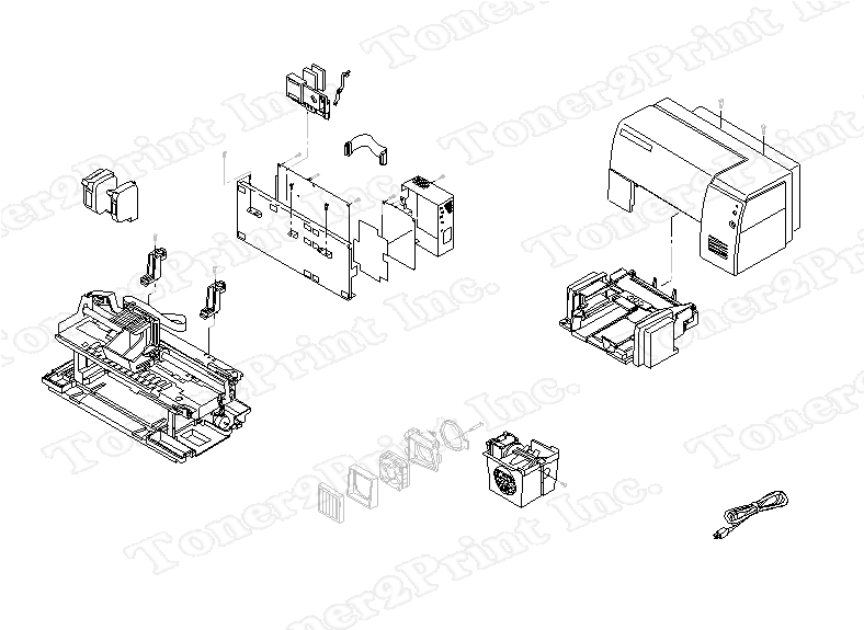
C2145-67810 is represented by #3 in the diagram below.
- 1
- 1 C2145-40110 - Top cover bracket - Installed between old style ground plane and top cover
- 1
- 1 C2145-40110 - Top cover bracket - Installed between old style ground plane and top cover
- 2
- 2 C2145-80014 - Power supply insulator - Insulates power supply from chassis
- 4
- 4 C2145-00016 - Power supply cover - Shields and protects power supply PC board
- 5
- 5 C2145-60025 - Power cable - Has two 9-pin (F) connectors - 3.4cm (1.3in) long
- 6
- 6 C2145-40046 - Door actuator - Actuates access door open switch
- 8
- 8 9170-1627 - Ferrite assembly - Installed on flex cable assembly
- 16
- 16 C4555-00010 - Ground plane - Grounds power supply and logic PCA
1
C2145-40110
Bracket
Top cover bracket - Installed between old style ground plane and top cover
2
C2145-80014
Insulator
Power supply insulator - Insulates power supply from chassis
4
C2145-00016
Cover
Power supply cover - Shields and protects power supply PC board
5
C2145-60025
Cable
Power cable - Has two 9-pin (F) connectors - 3.4cm (1.3in) long
6
C2145-40046
Actuator
Door actuator - Actuates access door open switch
8
9170-1627
Ferrite Assembly
Ferrite assembly - Installed on flex cable assembly
16
C4555-00010
Ground
Ground plane - Grounds power supply and logic PCA
|