| |
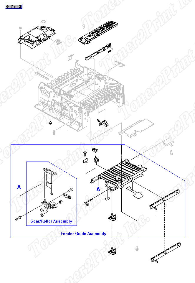
C2005-69005 is represented by #4 in the diagram below.
Internal Assemblies
- 2
- 2 RG5-1814-000CN - Small media roller assembly - Mounts on the bottom of the plate in the feeder guide assembly
- 3
- 3 RG5-1691-000CN - Feeder guide assembly - Ribbed plastic plate with sensor lever and media roller assembly
- 5
- 5 RG5-0672-000CN - Toner cartridge lever (White) - On left side of feeder guide
- 6
- 6 RG5-0711-020CN - Top oblique roller assembly - Top/front guide with roller on left
2
RG5-1814-000CN
Roller
Small media roller assembly - Mounts on the bottom of the plate in the feeder guide assembly
3
RG5-1691-000CN
Guide
Feeder guide assembly - Ribbed plastic plate with sensor lever and media roller assembly
5
RG5-0672-000CN
Lever
Toner cartridge lever (White) - On left side of feeder guide
6
RG5-0711-020CN
Roller
Top oblique roller assembly - Top/front guide with roller on left
|