| |
RH7-5354-000CN is represented by #4 in the diagram below.
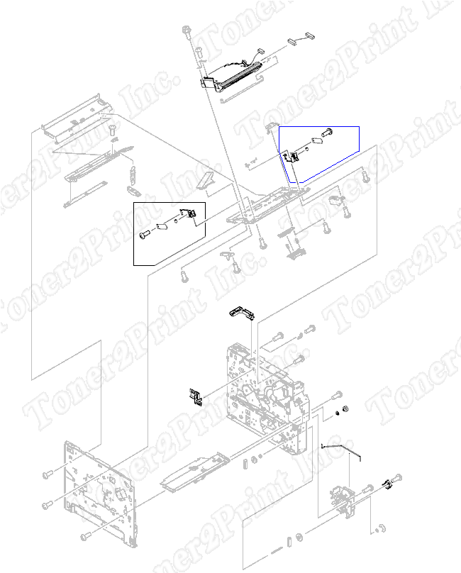
- 2
- 2 RM1-0054-000CN - Right side shutter assembly - Blocks light from scanner on right side
- 3
- 3 RC1-0268-000CN - Metal rod between external power button and switch on power supply board
- 7
- 7 RM1-0053-000CN - Left side shutter assembly - Blocks light from scanner on left side
- 8
- 8 RC1-0264-000CN - Feed roller shaft bushing - Bushing on right side of printer that supports the feed roller shaft.
- 9
- 9 RU5-0045-020CN - 18 tooth gear - Located on right side of printer in the Tray 2 paper pickup assembly
2
RM1-0054-000CN
Shutter
Right side shutter assembly - Blocks light from scanner on right side
3
RC1-0268-000CN
Rod
Metal rod between external power button and switch on power supply board
4
RH7-5354-000CN
Solenoid
Tray 2 pick-up solenoid - Mounts on the paper pick-up drive assembly
7
RM1-0053-000CN
Shutter
Left side shutter assembly - Blocks light from scanner on left side
8
RC1-0264-000CN
Bushing
Feed roller shaft bushing - Bushing on right side of printer that supports the feed roller shaft.
9
RU5-0045-020CN
Gear
18 tooth gear - Located on right side of printer in the Tray 2 paper pickup assembly
|